
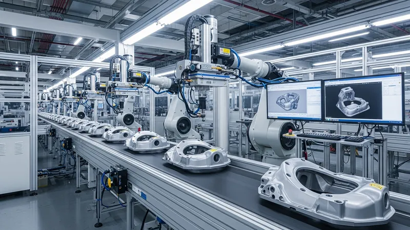
Automated dimensional inspection refers to the use of technology-driven systems that measure the physical attributes of objects, mainly components produced in manufacturing environments. Such systems typically incorporate devices like sensors and imaging tools combined with software algorithms to evaluate shapes, sizes, and geometric features rapidly on assembly lines or during quality assessment phases. Automated dimensional inspection is designed to systematically capture data on manufactured parts to determine conformity with predefined specifications, aiming to detect deviations that could impact product functionality or compatibility.
This approach generally utilizes non-contact or contact measurement methods, depending on the application and component characteristics. Measurement accuracy, repeatability, and data processing capabilities are central factors in assessing the effectiveness of an automated dimensional inspection process. Various configurations can be adopted for these systems, tailored to measurement complexity, production volume, and integration requirements within manufacturing workflows. The technology enhances the ability to perform consistent inspections with decreased manual intervention, though implementation can vary based on industry and inspection objectives.
Laser scanning systems may offer comprehensive surface data useful in reverse engineering or validating complex geometries, with typical system costs varying based on resolution and speed capabilities. Coordinate measuring machines are frequently employed when stringent tolerances are required and often come with software suites for data analysis and reporting. Vision-based measurement systems provide flexibility in inspecting multiple features rapidly, utilizing image processing methods to derive dimension data, often suitable for inline quality monitoring. Selection among these types depends on factors such as required accuracy, part complexity, and environmental conditions within production zones.
Data capture methodologies in automated dimensional inspection depend heavily on sensor types and system calibration procedures. Sensors can involve contact probes, optical cameras, lasers, or structured light sources, each delivering different data quality and resolution levels. The integration of software platforms enables real-time analysis, filtering, and decision-making support, which may affect throughput and operator intervention frequency. Effective data handling also helps in generating traceable records for compliance and quality audits, making the process essential in regulated manufacturing sectors.
Measurement accuracy principles in automated dimensional inspection relate to system calibration, environmental stability, and measurement technique. Calibration practices typically address sensor alignment, probe tip compensation, and reference standard adherence to ensure results fall within acceptable uncertainty ranges. Environmental factors such as temperature, vibration, and light conditions may influence measurement precision and are usually monitored or controlled sufficiently. Understanding these variables is crucial for interpreting inspection data with appropriate consideration of potential deviations or sensor limitations.
Quality control workflows integrating automated dimensional inspection often encompass predefined acceptance criteria, sampling plans, and reporting mechanisms. Workflow design ensures that measured data correlate with manufacturing process control parameters to identify trends and potential issues promptly. Automated inspection results can feed into statistical process control (SPC) systems, enabling ongoing quality evaluation and corrective action planning. The interplay between inspection outputs and manufacturing adjustments can contribute to consistent product standards and potential reductions in defect rates.
In summary, automated dimensional inspection involves the systematic measurement of physical component features through various sensor-based technologies and analytical software. Different types of systems exist to handle diverse inspection needs, each with distinct data capture and accuracy considerations. The integration of these systems supports quality control frameworks within manufacturing, potentially enhancing consistency and traceability. The next sections examine practical components and considerations in more detail.
Automated dimensional inspection systems are categorized primarily by their measurement principles and sensor technologies. Laser scanning systems, coordinate measuring machines (CMM), and vision-based systems represent common types employed across industries. Laser scanners typically work by projecting laser lines or points onto surfaces, creating comprehensive point clouds that represent the object's shape. This is valuable for complex geometries but might require post-processing to extract specific dimensions.
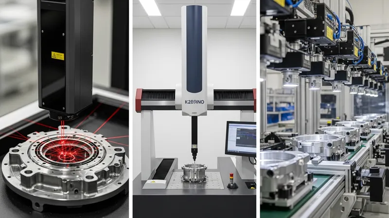
Coordinate measuring machines operate with tactile or scanning probes that physically contact components at selected points to gather coordinate data. These systems are often found in quality laboratories or production environments where precision is a priority. Vision-based systems employ optical cameras and lighting to capture images analyzed via algorithms that recognize features and edges, suited for inline inspection with less physical interaction.
Hybrid systems are also possible, combining elements of laser scanning with vision or tactile measurements to improve accuracy or adapt to various component types. Each system’s suitability depends on factors like surface finish, material, dimensional complexity, and production volume. Typically, manufacturers balance inspection thoroughness with operational efficiency, choosing systems aligned with their production demands.
In terms of implementation, system selection may also factor in cost considerations, including hardware investment and maintenance. Laser scanning equipment and CMMs commonly represent higher capital expenses and may require skilled operators. Vision systems might be more cost-effective for high-volume, simpler dimension checks but could lack some precision achievable by tactile methods. Understanding these attributes can help in framing inspection approaches within manufacturing quality strategies.
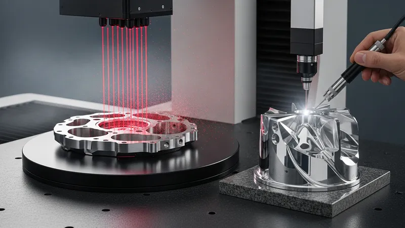
Effective data capture in automated dimensional inspection relies on the interaction between sensing technology and software interpretation. Laser-based sensors capture dense point clouds by reflecting laser light off a surface, which are then processed to build three-dimensional models. This method provides comprehensive surface information, although it may be sensitive to reflective or transparent materials.
Tactile probes in devices like CMMs collect discrete measurements at predefined contact points. These readings require stable setups and controlled environments to minimize measurement variations. The tactile approach allows for precise dimension readings, particularly on machined or engineered surfaces, but generally involves longer cycle times than optical methods.
Vision-based systems utilize digital cameras combined with controlled lighting conditions to capture images of components. Software algorithms then analyze these images to detect edges, contours, or geometric features, converting visual data into quantifiable measurements. This non-contact method is often used for faster assessments and can be integrated directly on production lines for immediate feedback.
Structured light scanning is another data capture technique where patterns of light, often stripes, are projected onto a surface. Distortions in these patterns allow software to calculate shapes and surface profiles. This technique adds versatility for inspecting complex components and may achieve reasonable accuracy in a controlled environment. Data capture methods vary in their suitability depending on inspection speed, required detail, and part characteristics.
Achieving reliable measurement accuracy in automated dimensional inspection depends heavily on calibration processes and system design. Calibration involves adjusting sensor outputs to correspond with known standards or reference artifacts, helping to align measurement data to traceable benchmarks. Regular calibration is often conducted to maintain instrument precision as environmental factors and wear can influence sensor performance over time.
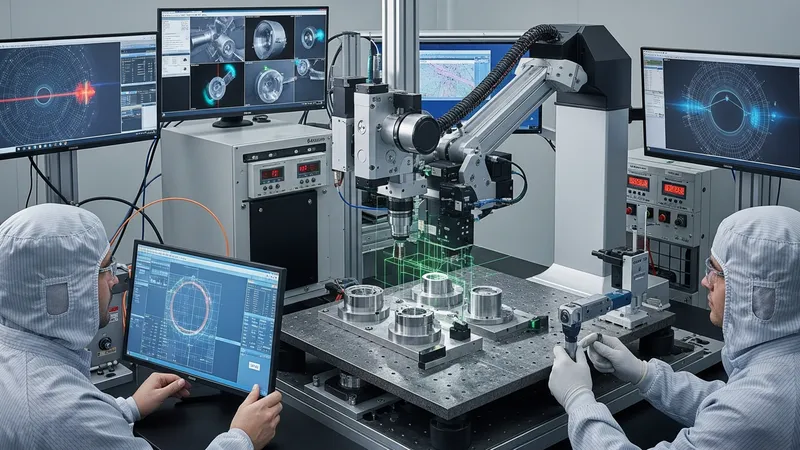
Environmental stability such as temperature control is particularly relevant, as thermal expansion or contraction can affect both parts and measuring devices. Vibrations or airborne particles within production settings might also interfere with sensitive measurements, and appropriate safeguards or isolation methods may be employed. Understanding and managing these variables contributes to maintaining consistent inspection results.
The software used in these systems plays a role in compensating or adjusting for expected measurement variations. Algorithms may apply filtering, noise reduction, or geometric fitting techniques to refine raw sensor data. However, the interpretations are typically subject to uncertainty ranges dictated by sensor resolution, calibration quality, and environmental conditions.
When comparing different inspection methods, tactile measurements can offer finely detailed point data but might take longer and be influenced by probe condition. Optical methods generally allow faster scanning with broad surface data but could be less precise on reflective or transparent materials. Hence, accuracy considerations must account for both equipment capabilities and operational context to appropriately assign confidence levels to inspection outcomes.
Automated dimensional inspection systems often form integral parts of manufacturing quality control workflows. Inspection results are typically benchmarked against tolerances or specifications established during product design and process planning. These acceptance criteria define whether components meet dimensional requirements or may require rework or rejection.
Inspection data can be collected on a sampling basis or for comprehensive part evaluations, depending on manufacturing volume and quality risk assessments. When integrated with statistical process control systems, dimensional data helps identify trends or potential process deviations early in production runs. This enables manufacturers to address manufacturing variability proactively.
Data reporting features commonly include trend analyses, deviation highlighting, and detailed measurement records that support traceability and compliance documentation. Some systems can automatically flag out-of-spec conditions, although decisions regarding disposition typically involve human verification in production environments.
The workflow integration also considers the impact of inspection cycle times and system interface compatibility with manufacturing execution systems (MES). Proper synchronization helps avoid bottlenecks while maintaining effective quality monitoring. As automated inspection technology evolves, its collaboration with broader quality management frameworks continues to develop, aiming to enhance manufacturing consistency without adding undue complexity.