
Container-based residential construction uses repurposed intermodal steel boxes as primary building components, combined with carpentry, mechanical, and finishing trades.
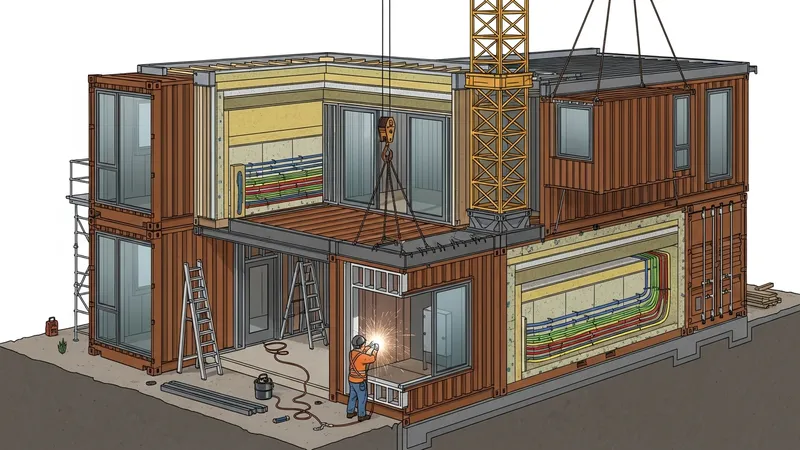
Contemporary practice around these dwellings involves a mix of factory prefabrication and on-site adaptation. Fabrication steps may include corrosion remediation, surface treatment, added insulation, and airtight detailing prior to final cladding. Mechanical, electrical, and plumbing runs can be routed inside stud cavities or externally in service zones. Design attention typically centers on thermal performance, moisture control, structural reinforcement where openings are introduced, and connections between stacked or side-by-side units to manage loads and water shedding.
Structural reinforcement methods often combine engineered steel components with conventional framing. After substantial openings or when stacking multiple units, designers may add I-beams, C-channels, or boxed headers to re-establish continuous load paths. Connection details between containers frequently use bolted splice plates or welded joints; when welding is used, corrosion protection and heat-affected zone treatment typically require attention. Reinforcement strategies may vary by seismic, wind, and snow load requirements, and engineers commonly model altered sections to estimate member sizes and required connections rather than relying on unmodified container ratings.
Insulation approaches vary by climate and interior finishing. Closed-cell spray foam can provide a vapor-impermeable layer and additional stiffness but may increase cost and complicate future repairs. Mineral wool or fibrous batt systems with a ventilated rain screen can help manage moisture accumulation on exterior steel and allow for reversible assemblies. Structural thermal breaks or continuous insulation layers are often introduced to reduce thermal bridging through the steel shell; designers may balance interior square footage loss against performance gains when selecting insulation systems.
Modular stacking and connector systems are central to scaling container assemblies. Aligning corner castings and using supplemental brackets can preserve the container’s designed load transfer while allowing lateral load sharing across multiple units. Prefabricated connector frames that pick up roof and floor loads can simplify on-site work and reduce time exposed to weather. Designers may also plan for tolerances in site grading and foundation work so that connectors engage without undue stress, and consider temporary bracing sequences during erection to control deformation.
Integrating these methods influences mechanical and finish selections. For example, interior finishes over added insulation may require furring to avoid thermal bridging and permit service chase routing. HVAC sizing for compact volumes often favors ductless systems or small-duct designs, while moisture-prone climates may call for conditioned ventilation to control condensation on steel surfaces. Electrical and plumbing routing may be planned with prefabricated wall panels or in exposed service cavities to ease future maintenance. Each choice can affect lifecycle maintenance and retrofitability.
In summary, repurposed shipping containers combined with conventional construction techniques form a building system that may require supplemental framing, tailored insulation, and engineered connector systems to meet performance expectations. Design teams often weigh trade-offs involving thermal bridging, moisture management, structural continuity, and transportability. The next sections examine practical components and considerations in more detail.
Reinforcement is often the first technical adjustment after modifying container shells. Cutting large openings for glazing or combining multiple units can interrupt the container’s original corner-bearing load path, so engineers commonly evaluate the altered geometry and specify added members such as boxed headers, C-channels, or continuous steel beams. Connections between new members and the existing shell may be bolted or welded; choice of method typically depends on available equipment, corrosion protection strategy, and expected movement. Temporary bracing during on-site modification is frequently used to control distortion until permanent elements are installed.
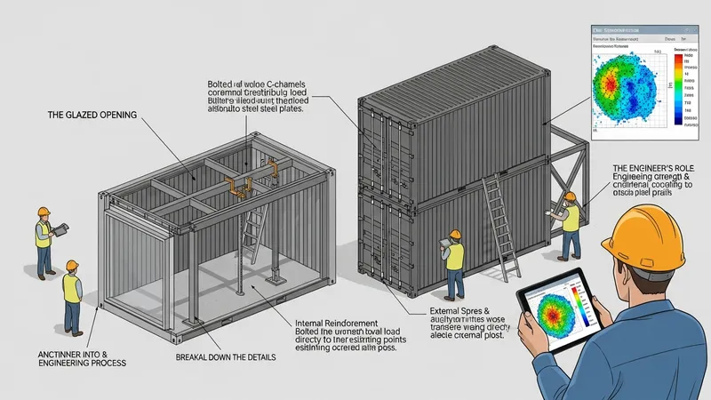
Load transfer between stacked containers usually relies on corner post alignment and supplemental plates or frames. When units are stacked more than two levels or span uneven loads, designers may introduce internal columns or external support frames to distribute vertical and lateral forces. Seismic and wind design considerations can necessitate diaphragms and cross-bracing to meet local codes. Engineering assessments often use finite element or simplified frame models to estimate stresses around cut-outs and to size reinforcement members conservatively without assuming unmodified container capacities.
Material condition and corrosion history affect reinforcement choices. Used containers may have localized corrosion near doors or on floor plates; addressing these conditions often involves removing degraded metal, applying rust converters, and welding in patch plates before adding reinforcement. Protective coatings, galvanic break measures, and maintenance access are important components of a long-term strategy. Designers sometimes prefer removable or replaceable reinforcement details that allow for inspection and future repair without major disassembly.
Construction sequencing influences reinforcement complexity. Off-site prefabrication of reinforcement frames can reduce on-site welding and exposure to weather, while site-installed splice plates may simplify transport. When reinforcement members are integrated with roof or floor systems, coordination with insulation and service runs is essential to avoid conflicts. Clear shop drawings that show how reinforcements interface with finishes and building systems typically reduce rework and help ensure the final assembly performs as modeled.
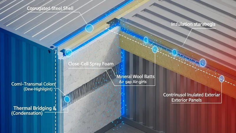
Thermal performance in steel shell structures can be challenging because the metal conducts heat and cold rapidly, producing thermal bridging where the shell intersects interior finishes. Insulation approaches commonly used include closed-cell spray foam applied directly to the interior shell, mineral wool in furring channels with an air gap, and insulated panel overlays that add continuous insulation on the exterior. Each method may influence condensation behavior differently; assemblies that allow drying in at least one direction often reduce long-term moisture risk compared to fully vapor-impermeable systems.
Condensation control strategies typically combine thermal design with controlled ventilation. Continuous insulation or thermal breaks at junctions reduce cold spots that attract moisture, while mechanical ventilation with heat recovery may manage humidity in tight volumes. Designers sometimes use hygrothermal analysis to predict dew-point locations within wall assemblies, particularly in climates with large seasonal humidity swings. Where interior finishes are placed directly over insulation, service routing and inspection access should be considered to avoid concealed moisture accumulation.
Fire safety and acoustic requirements also influence insulation selection. Mineral wool can provide both thermal and acoustic attenuation and is non-combustible, while spray foam can add structural rigidity and air sealing but may require additional measures for fire separation and off-gassing control. Acoustic partitions between units may be added via double stud walls or resilient channels to mitigate low-frequency transmission through metal shells. Compliance with local building codes regarding insulation materials and fire barriers remains a common driver of product choice and detailing.
Installation quality matters for long-term performance. Ensuring continuous coverage without gaps, controlling compression of batt materials, and sealing interfaces around penetrations reduce thermal bypass and moisture entry. Prefabricated insulated panels or cavity insulation installed in a factory setting may achieve more consistent results than entirely field-applied systems, although transport dimensions and site access can limit panel sizes. Designers often document expected performance ranges rather than absolute values, noting that actual outcomes depend on workmanship and climatic exposure.
Modular strategies for container assemblages often rely on repeatable connector details that allow units to be stacked, splayed, or offset while preserving structural continuity and weatherproofing. Typical connector types include bolted splice plates between cut framing members, custom steel brackets that pick up roof loads, and adapter frames that align container corners to foundations. Designers frequently plan for tolerances in site conditions so connectors can be engaged without inducing unintended stresses; adjustable shims and grout pads are common tools to manage small misalignments.
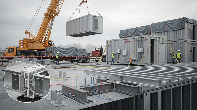
Transport and handling constraints shape module dimensions and connector design. Standard container widths and heights inform interior planning and orientation of service cores, while openings for cranes, trucks, and staging areas guide erection sequencing. Prefabricated service modules that house plumbing and electrical risers may be installed as discrete units before enclosure, which can simplify final connections. Sequencing plans that describe temporary bracing, lifting points, and weather protection typically reduce on-site risk and help maintain schedule predictability.
Weather and sealing details at connectors are vital for durability. Flashing, overlapping membranes, and rain screen principles are often applied where units join to prevent water intrusion. Designers may use continuous roof and wall membranes that bridge connectors or employ gasketed flange systems to allow movement while preserving watertightness. Thermal bridging at connector lines can be reduced by introducing insulated plates or thermal break spacers, balancing structural continuity with energy performance goals.
Service integration and future adaptability are factors in connector planning. Creating accessible cavities at connection zones makes it easier to route and maintain utilities between modules. Where future reconfiguration is a consideration, designers may prefer mechanical, bolted connectors that can be disassembled rather than permanent welded splices. Documentation of as-built connector locations and reinforcement details supports maintenance and helps future owners understand the assembly’s limitations and capacities.
Material choice influences longevity and maintenance needs in container-based dwellings. Corten steel offers atmospheric corrosion resistance when properly maintained, but areas subject to pooling water or abrasive wear may still require local corrosion control. Interior finishes and insulation materials are selected not only for thermal properties but also for compatibility with metal substrates and for ease of repair. Designers may favor assemblies that permit periodic inspection of critical interfaces, such as welded reinforcements and connector plates, to identify early corrosion or fatigue.
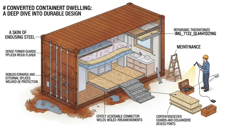
Lifecycle thinking often includes repairability and potential reuse. Details that facilitate replacement of floor panels, external cladding, or insulation layers can extend service life and reduce embodied waste. Where units are transported multiple times, robust corner and splice protection may minimize damage. Designers sometimes quantify typical maintenance tasks and intervals as part of project planning so that stakeholders can anticipate access needs and ongoing costs without assuming exceptional durability without upkeep.
Environmental and embodied carbon considerations frequently connect back to insulation and reinforcement choices. Using lower-carbon insulation materials or designing for minimal added steel can reduce embodied impacts, while modular reuse and adaptability may lower lifetime resource consumption. Metrics and modeling may be used to compare scenarios, but results often depend on assumptions about service life, maintenance, and eventual deconstruction pathways rather than being intrinsic to a single material choice.
Cost and regulatory drivers intersect with technical choices. Local building codes, fire separation requirements, and wind or seismic design loads typically define minimum reinforcement and insulation levels, and permit processes can affect prefabrication strategies. Budgets may influence the balance between factory work and field adaptation; designers often present several assembly options that show how different insulation or reinforcement approaches may trade off upfront cost, on-site labor, and long-term maintenance needs. Continued reading of technical references and local regulations can inform these trade-offs without implying singular solutions.